Picking The Terrain
The first piece of information needed when morphing a terrain is to find out where the user wants to morph the terrain. By using a small equation with the DirectX D3DXIntersect() function we can determine where the user wishes to pick the terrain. Here is a good place to get started and learn how the basics of D3DXIntersect() works.
Once the basic functionality of D3DXIntersect() is implemented you can use this equation to determine the exact position that the user is picking.
Picked Position = Origin + (Direction * Distance)
Next, you can do a simple distance calculation to create a list of vertex positions’ that lie inside the defined radius. This becomes your list of vertices to modify. So when morphing is applied it will only be applied to these vertices.
Morphing Up
I morphed the terrain up with respect to the distance a vertex point was from the picked position. First I determined the scale of the morph based on its distance away from the center of the terrain and the radius of the defined brush.
Scale = cos( PI/2 * ( Brush Radius – (Brush Radius – Distance) ) / Brush Radius)
Then I added the scaled user defined increment to the vertex’s Y position. This produces a smooth cosign curve over the picked position.
By passing in a negative increment value, the Morph Up function becomes a Morph Down function. Doing the equivalent shape of Morph Up, but in the negative/downward direction.
Smoothing
Smoothing the terrain is quite simple and is basically averaging all of the selected vertices’ heights. First, get the average height of all the selected vertices. Next, get the difference between the average height and the current vertex height. Finally, scale the difference and add it back to the original height. The scale is specified by the user.
Vertex Y Position = Vertex Y Position + Scale * (Average Height – Vertex Y Position)
By passing in a negative scale the Smooth function becomes an Extrude function. Moving the vertices away from the average height position.
Updating The Terrain
Locking Vertices and Indices of a mesh can be fairly process intensive. So when doing this type of editing it can be helpful to store the Vertices and Indices in a local array or list. Then make all your edits to the locally stored Vertex and Index lists and set a flag to signal that the mesh needs to be updated. This allows for you to make multiple edits to the same vertices and only lock the mesh once for the final updated vertex.
Helpful Thing I Learned
In order to edit a ID3DXMesh you will not be able to use a managed pool of memory. So the locally stored vertices and indices also help in reconstructing the mesh after the device has been lost and reset.
Even though you may not make any changes to the Indices within the index buffer of the mesh. I found that I needed to still reset the indices at the same time I reset the vertices.
If you are doing any light calculations it is nice to recalculate the normals after updating the vertices.
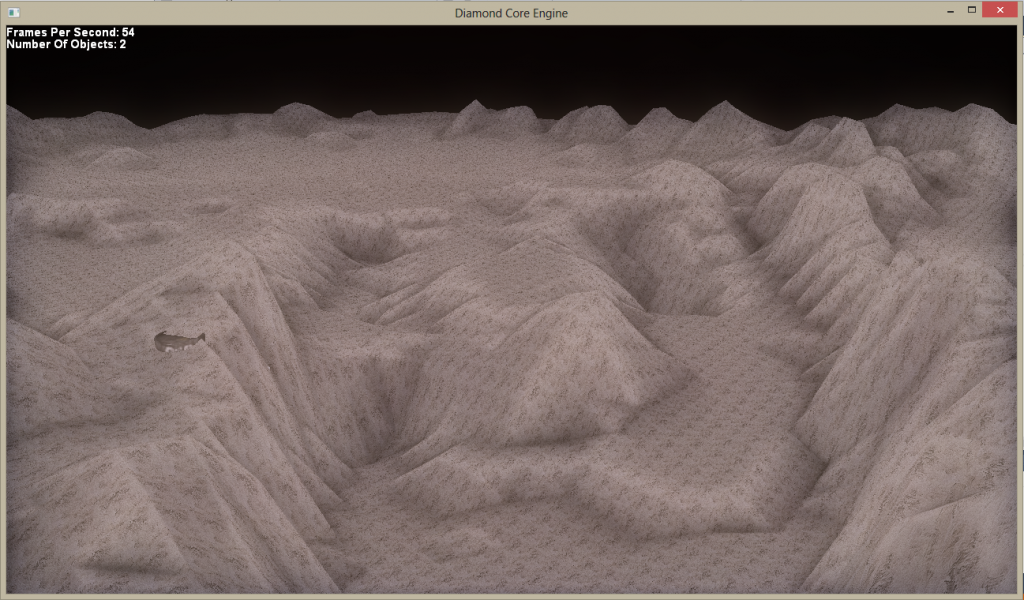
Using some sort of shadowing can help define the shape of the terrain. I used my modified SSAO shader to dynamically give detail to the curves of the terrain.